


 NEWS
NEWS
HOME > News
NEWS
2013-05-13
20130513 Safety Information
General electrical and electronic products in the circuit will always be part of the transformer,
the transformer safety indicators is extremely important. Safety requirements are divided into
two categories, transformers transformer should meet the creepage distance between primary
and secondary circuits, electrical clearance requirements, and transformer overload requirements.
In this paper, a brief introduction on the transformer safety requirements IEC / EN 60950-1 standard,
for example.
Transformer creepage distance and clearance requirements
Transformer production to meet process requirements, should use the wall tape, sleeve or triple
insulated wire, etc. to ensure the clearance and creepage distances to meet.
Tape (Tape): Under certain conditions, there is no thickness requirements, but use at least 2
layers, and each layer can be individually through the corresponding withstand voltage test,
if the layer 3, layer 2 together can be passed The corresponding voltage test (usually 3000Va.c).
Skeleton (Bobbin): thickness of at least 0.4mm, flammability rating of V-2 the ball pressure
(Ball Pressure) test.
The work in the primary circuit of the rated supply voltage is less than 300V, the circuit repetitive
peak voltage exceeds the peak value of the supply voltage, the minimum electrical clearance
should be the sum of the following two values:
Used in the IEC/EN60950-1 Table 2L sure creepage distance operating voltage:
- Should use the actual rms or dc value;
- If you use the DC value of any superimposed ripple voltage should be negligible;
- Does not consider short-term (such as TNV circuit rhythm ringing signal);
- Does not consider short-term interference (for example: transient).
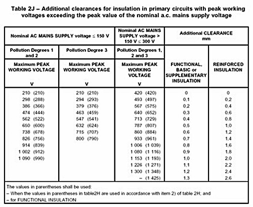
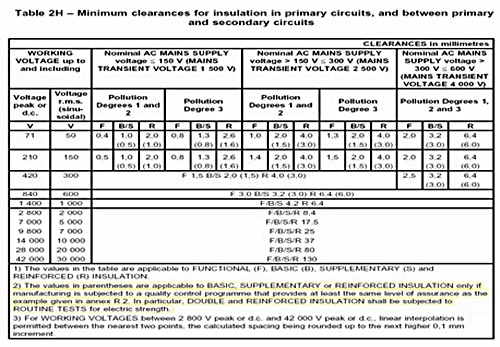
- The IEC/EN60950-1 Table 2H insulation working voltage equal to the mains power supply
voltage minimum clearance;
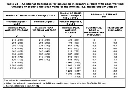
- The IEC/EN60950-1 Table 2J applicable additional clearances value.
Transformer overload requirements.
The transformer in the maximum specified load status of each secondary coil in turn separate
diode load, adjust the size of the load until the maximum power output before the transformer
protection.
If the initial point of the transformer protection soon, then re-select a 10-20% reduction in output
power. When the temperature is stable and then gradually increase the load, and at the same time
monitoring the temperature. When the temperature is stable again, a part of the load increase, and
this process continues until the transformer so that the device is operated until the final results
(open Component instance, fire, etc.) or to reach thermal equilibrium. Test Aborted reliable
components (such as column names / approved fuse authorized insurer resistance) open circuit,
it is necessary to use the new components of the test was repeated twice more (a total of three
times). Record the maximum temperature in the pre-protection. This method also applies to equipment
with over-temperature protection.
the transformer safety indicators is extremely important. Safety requirements are divided into
two categories, transformers transformer should meet the creepage distance between primary
and secondary circuits, electrical clearance requirements, and transformer overload requirements.
In this paper, a brief introduction on the transformer safety requirements IEC / EN 60950-1 standard,
for example.
Transformer creepage distance and clearance requirements
Transformer production to meet process requirements, should use the wall tape, sleeve or triple
insulated wire, etc. to ensure the clearance and creepage distances to meet.
Tape (Tape): Under certain conditions, there is no thickness requirements, but use at least 2
layers, and each layer can be individually through the corresponding withstand voltage test,
if the layer 3, layer 2 together can be passed The corresponding voltage test (usually 3000Va.c).
Skeleton (Bobbin): thickness of at least 0.4mm, flammability rating of V-2 the ball pressure
(Ball Pressure) test.
The work in the primary circuit of the rated supply voltage is less than 300V, the circuit repetitive
peak voltage exceeds the peak value of the supply voltage, the minimum electrical clearance
should be the sum of the following two values:
Used in the IEC/EN60950-1 Table 2L sure creepage distance operating voltage:
- Should use the actual rms or dc value;
- If you use the DC value of any superimposed ripple voltage should be negligible;
- Does not consider short-term (such as TNV circuit rhythm ringing signal);
- Does not consider short-term interference (for example: transient).
- The IEC/EN60950-1 Table 2H insulation working voltage equal to the mains power supply
voltage minimum clearance;
- The IEC/EN60950-1 Table 2J applicable additional clearances value.
Transformer overload requirements.
The transformer in the maximum specified load status of each secondary coil in turn separate
diode load, adjust the size of the load until the maximum power output before the transformer
protection.
If the initial point of the transformer protection soon, then re-select a 10-20% reduction in output
power. When the temperature is stable and then gradually increase the load, and at the same time
monitoring the temperature. When the temperature is stable again, a part of the load increase, and
this process continues until the transformer so that the device is operated until the final results
(open Component instance, fire, etc.) or to reach thermal equilibrium. Test Aborted reliable
components (such as column names / approved fuse authorized insurer resistance) open circuit,
it is necessary to use the new components of the test was repeated twice more (a total of three
times). Record the maximum temperature in the pre-protection. This method also applies to equipment
with over-temperature protection.